
 Agrandir l'image
| Maximum Gain: | Approximately 17 dB |
| Frequency Response (with Input Attenuator set to -6 dB): | 20 Hz to 20 kHz +/– 1.3 dB |
| Frequency Response (with Input Attenuator set to 0 dB, Zsource = 100 1): | 15 Hz to 53 kHz +/– 1.3 dB |
| Line Input: | 600 1 floating transformer balanced |
| Sidechain Input Impedance: | 1200 1 floating transformer balanced |
| Line Output Impedance: | 120 1 floating transformer balanced, internally terminated by 1800 1 |
| Minimum Recommended Load Impedance: | 600 1 |
| Signal to Noise Ratio: | > 85 dB |
| Max. Output Level for 1% THD (no limiting): | +28 dBu |
| THD + Noise at +4 dBu (no limiting): | 0.02% |
| THD + Noise at +4 dBu (10 dB limiting): | 0.7% |
| Recommended Upper Limit of Compression for High Fidelity: | 12 dB |
| Power Requirements: | 120V 60 Hz or 240V 50 Hz, 240 Watts MAX |
| Dimensions: | 19” (483 mm) width 14” (356 mm) depth 7” (178 mm) height |
| Unit Weight: | 34 lbs (15.5 kg) |
| Shipping Weight: | 37 lbs (16.8 kg) |
ELECE4614E
Nouveau
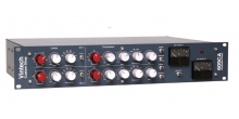
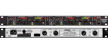
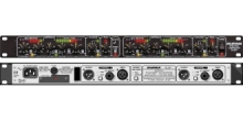
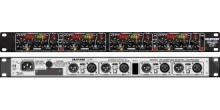
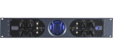
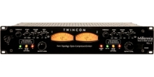
ELECTRONAUT - M97

The M97 is a modern take on an idea that has been evolving for 70 years — a triode amplifier with a variable amplification factor (expressed mathematically as ‘µ’ or ‘mu’), configured to provide dynamic range compression and limiting for high-quality audio.
This project took several years to complete, and involved a huge amount of brainstorming, experimentation, and trial and error, even before the first prototype was built. Many more hours were spent rethinking, redesigning, rebuilding, and refining. The process was grueling yet fascinating, exhausting yet exhilarating. (!!) Best of all, it resulted in what we believe is an outstanding modern variable-mu1 compressor with an excellent set of features and an amazing sound.
The Design Notes below shed some light on the philosophy behind the design, while also pointing out some of the limitations found in traditional vari-mu compressors, and the solutions Electronaut devised in order to achieve a tangible improvement.
FRONT PANEL FEATURES
THRESHOLD CONTROLS
The AC and DC threshold controls affect the audio reaching the controlling amplifier, and therefore determine the type of compression or limiting the M97 performs. Both Threshold controls are 24-position stepped attenuators built on Elma rotary switches.
The AC Threshold acts as an input attenuator to the controlling amplifier; it controls the amount of limiting action, and effectively, the slope of the compression curve.
The DC Threshold selects the portion of the audio waveform that reaches the controlling amplifier, affecting the limiter’s response.
INPUT ATTENUATOR
The Input Attenuator is a 1 dB/step 24-position stepped attenuator, built on a 3-pole Elma rotary switch, and configured as a balanced bridged-T attenuator with an impedance of 600 ohms.
The attenuator is placed between the input XLR and the input transformer, with an OFF (mute) function at the most counterclockwise position and a “soft-bypass” function at the 0dB position. The 0 dB setting makes it possible to achieve extended high-frequency response, as described below.
Achieving Extended High Frequency Response using the 0 dB setting
Due to the compounded parasitic capacitance caused by the sheer number of tubes used in the audio amplifier, classic compressors like the Fairchild 660/670 exhibit a high frequency roll-off of several dB at 20 kHz. This is part of the characteristic “sound” associated with this type of compressor, and was considered an acceptable trade-off for the other benefits of using so many tubes. The M97 offers the best of both worlds: “classic” high-frequency response, and an “extended” high-frequency option.
When the INPUT ATTENUATOR is set to any value between 1 dB and 22 dB, the impedance of the signal reaching the input transformer is set by the input attenuator, and the high-frequency response resembles the Fairchild. When the Input Attenuator is set to 0 dB, the impedance is determined by the output impedance of the device preceding the M97. Since modern D/A convertors exhibit a moderately low output impedance (typically between 25 and 100 ohms) the signal is less affected by the parasitic capacitance of the tubes, and the high-frequency response will be extended to nearly 50 kHz +/- 1 dB.
Since the AC and DC THRESHOLD controls determine the shape of the compression curve, and the INPUT ATTENUATOR determines where the signal is positioned along the curve, once the Threshold controls have been set the amount of limiting is ultimately controlled by the Input Attenuator. When using the 0 dB setting for extended high-frequency response, it will be necessary to adjust the amount of level reaching the M97 at the source in order to control the rate of limiting.
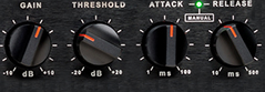
ATTACK and RELEASE
The attack and release controls are continuously-variable low-noise potentiometers, providing up to 50 µS attack time. The attack and release controls are interdependent. In the extreme counterclockwise positions of the attack and release controls, the limiter is intended primarily for peak limiting; where it is desirable to only trim transients and not limit the basic program material’s dynamic range.
HIGH PASS SWITCH
The FLAT/120Hz switch determines the bandwidth of the signal being fed to the controlling amplifier, and therefore the frequency response of the limiting action. Setting the switch to 120 Hz inserts a 6 dB/octave high pass filter with a -3 dB point at 120 Hz into the input of the controlling amplifier.
The high-pass filter can be useful to help keep the limiter from tracking very low frequency program material.
BYPASS/COMPRESS/PASS SWITCH
This toggle switch provides three distinct routing modes:
BYPASS – A signal appearing at the INPUT XLR is hardwired directly to the output, bypassing the audio and controlling amplifiers.
COMPRESS – A signal appearing at the INPUT XLR is routed through the audio amplifier to the output. The gain of the audio amplifier is determined by the limiting action.
PASS – A signal appearing at the INPUT XLR is routed through the AUDIO amplifier, which operates as a fixed-gain line amplifier with a gain of approximately 18 dB. In PASS Mode, the controlling amplifier is disconnected and has no effect.
FUNCTION SWITCH
The M97 Compressor/Limiter has a front panel rotary FUNCTION switch, with five distinct modes: NORMAL, SIDECHAIN, SIDECHAIN/INTERLOCK, INTERLOCK, and EXTERNAL. They are described below in a different order for clarity.
NORMAL – The unit operates as a stand-alone limiter. Other limiters which are connected to the M97 through either the INTERLOCK or EXTERNAL buss connectors on the rear panel have no effect on its operation.
SIDECHAIN – A The limiter action is triggered by a separate audio signal appearing at the SIDECHAIN input XLR connector.
INTERLOCK – All limiters which are connected to the INTERLOCK buss connector are affected by the operation of all or one limiter – e.g., it is possible to synchronize one or more limiters for multi-channel use where the independent action would provide phase distortion under separate channel limiting.
NOTE: For stereo compression using two M97 Compressor/Limiters, both units should be set to INTERLOCK mode, and a 1/4” mono cable should connect the INTERLOCK jacks on the rear panels together. Because the INTERLOCK mode creates a control voltage for both limiters which is a SUM of the individual control voltages, it is possible to control the limiting action using any proportion of each channel as the stimulus signal – i.e. it is possible to control the limiting action on a stereo signal with just the left channel, just the right channel, or equal parts of both, simply by configuring each compressor differently or equally.
SIDECHAIN/INTERLOCK – The limiter action is triggered by a separate audio signal appearing at the SIDECHAIN input XLR connector. Simultaneously, all limiters which are connected to the INTERLOCK buss connector are affected by the opera- tion of one or all limiters – e.g., it is possible to synchronize one or more limiters for multi-channel use, while triggering one or all limiters with the sum of a separate sidechain multi-channel signal.
EXTERNAL – The CONTROLLING amplifier is disconnected from the limiter and the AUDIO amplifier is dependent on another limiter for its level control. A control-voltage appearing at the EXTERNAL buss connector will provide the bias to the AUDIO amplifier, and therefore set its gain.
NOTE: This buss connector requires a NEGATIVE voltage which can be as low as -150 VDC for full limiting. Diode protection is present to protect against the accidental application of a positive control voltage, as indicated on the rear panel by the diode symbol.
TONE/BALANCE
TONE MODE – When the TONE/BALANCE switch is set to TONE, the output is muted, and a low-distortion sine wave test tone is injected into the input of the M97. Used in conjunction with the meter, the tone makes it very easy to determine the ratio of compression and the threshold level for any combination of Threshold controls.
BALANCE MODE – As described in the “Philosophy” section, the balancing technique uses a precision sine wave test tone at the input and a narrow pass band filter at the output to isolate the level of 2nd harmonic distortion, and display it as a level on the meter. The balance is set by adjusting the 10-turn BALANCE calibration control until the minimum harmonic distortion is achieved.
NOTE: A precise balance is a theoretically correct target for minimum distortion. For distortion performance other than minimum, experiment at will! One advantage of having a precise balance control is the ease with which a recalibration for minimum distortion can be achieved after experimenting with other settings.
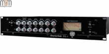
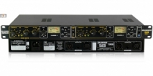
M97 METERING SYSTEM
The metering system in the M97 Compressor/Limiter represents a departure from the traditional analog meter approach. A 40 segment 40 dB Peak and Persistence meter, based on the ballistics of the Dorrough Electronics™ Loudness meter, is used in place of the usual “VU” or other analog milliammeter. Traditional analog meters typically display an RMS value of the limiting action, and are therefore unable to display a meaningful value when the compressor is set to provide transient peak reduction only. By contrast, the M97 meter has no problem tracking very fast transients, and can be relied upon as an indication of transient peak reduction. Several METER MODES have been designed into the system, offering a myriad of advantages and providing a clear picture of how the program material is being affected by the limiting action.
METER MODE KNOB
The meter is capable of several modes of display which are selectable using the center METER MODE knob. The modes are:
OFF: When the METER MODE knob is set to OFF, the M97 is in low-power stand-by mode. (See section on Low Power Standby, page XX)
ON: When the METER MODE knob is set to ON, power is applied to the main power transformer and the amplifier powers up. Allow at least 1 minute for the M97 to warm up upon startup.
INPUT: The meter displays the level of the audio appearing at the INPUT XLR connector, before it reaches the input attenuator.
ATTENUATOR: The meter displays the audio appearing after the INPUT ATTENUATOR. Naturally, an adjustment of the INPUT ATTENUATOR will display a corresponding change on the meter display. Since the meter and INPUT ATTENUATOR are both 1 dB per step, the meter and the attenuator correlate with a 1:1 relationship.
OUTPUT: The meter displays the audio appearing at the OUTPUT XLR connector.
GAIN REDUCTION: The meter displays a level corresponding to the amount of limiting action. When there is no limiting action, the meter will display a constant value of 0 dB. Limiting action is displayed in dB as a positive value, consistent with colloquial terminology – e.g., “6 dB of compression,” etc.
B+: The B+ meter mode converts the audio meter into a linear DC voltage meter, and is used to check the calibration of the power supply’s adjustable high-voltage regulator. A reading of 0dB indicates the power supply is perfectly calibrated to 325VDC. Any deviation from 0dB indicates a corresponding deviation from the 325V target, with each step representing a 1% error. Any reading within plus or minus 5% is acceptable.
REAR PANEL CONTROLS
325V ADJUST KNOB
The 325V Adjust control is a 10-turn potentiometer used for calibrating the high-voltage “B+” supply that powers the audio amplifier tubes. The voltage value is displayed on the meter when the meter is set to B+ Mode.
BALANCE/CHASSIS KNOB
A secondary balance control which is set at the initial time of calibration. Subsequent balance adjustments are done using the front panel BALANCE control.
MAINS VOLTAGE
A slider switch provides two options for mains voltage: 120V, and 240V.
ELECTRONICS
High voltage power supply is choke-filtered, tube regulated, and uses only polypropylene filter capacitors. (No electrolytics!)
TUBE COMPLEMENT
Audio Amplifier
Standard: Eight 5749W remote-cutoff pentode tubes wired as triodes.
Also accepts: 6386 remote-cutoff dual-triode, 6BA6, 12BA6, EF93
Controlling Amplifier
One 12AX7A dual-triode, one 12BH7 dual-triode, and two 6L6GC beam power pentodes.
Power Supply
One 12AX7A dual triode, and one 6AS7/6080 dual power triode
Features And Specs
| Maximum Gain: | Approximately 17 dB |
| Frequency Response (with Input Attenuator set to -6 dB): | 20 Hz to 20 kHz +/– 1.3 dB |
| Frequency Response (with Input Attenuator set to 0 dB, Zsource = 100 1): | 15 Hz to 53 kHz +/– 1.3 dB |
| Line Input: | 600 1 floating transformer balanced |
| Sidechain Input Impedance: | 1200 1 floating transformer balanced |
| Line Output Impedance: | 120 1 floating transformer balanced, internally terminated by 1800 1 |
| Minimum Recommended Load Impedance: | 600 1 |
| Signal to Noise Ratio: | > 85 dB |
| Max. Output Level for 1% THD (no limiting): | +28 dBu |
| THD + Noise at +4 dBu (no limiting): | 0.02% |
| THD + Noise at +4 dBu (10 dB limiting): | 0.7% |
| Recommended Upper Limit of Compression for High Fidelity: | 12 dB |
| Power Requirements: | 120V 60 Hz or 240V 50 Hz, 240 Watts MAX |
| Dimensions: | 19” (483 mm) width 14” (356 mm) depth 7” (178 mm) height |
| Unit Weight: | 34 lbs (15.5 kg) |
| Shipping Weight: | 37 lbs (16.8 kg) |