 Agrandir l'image
GRACB261B5
Nouveau
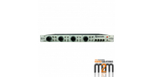
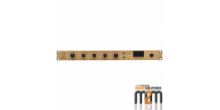
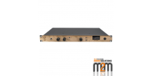
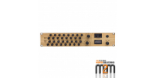
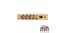
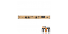
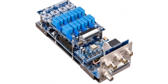
Grace Design - AES3 + ADAT CARD FOR M802

m802 A/D CONVERTER OPTION
The m802 A/D converter card option provides m802 users with state of the art A/D conversion for the most demanding music recording applications. The purpose for this new card is to provide A/D conversion technology capable of matching the transparent, musical character of our mic preamplifiers, with the combination of the two creating a new level of true audio purity. To understand what makes our A/D converter unique, the following is a discussionof our design's three basic functional blocks: the analog input stage, the A/D converter, and the clock generation (or regeneration).
ANALOG INPUT STAGE
Our converter's analog input circuitry is simple and pure. This fully differential circuitry contains no electrolytic capacitors and utilizes precision 0.5% tolerance thin film resistors, to ensure that there will be no signal coloration from capacitor dielectric absorption and resistor thermal modulation. Careful attention to grounding and power supply layout eliminates any sonic aberrations caused from unwanted interference from digital circuitry. The analog input amplifiers are powered from their own dedicated Voltage regulators and each analog power supply rail is double regulated to provide extreme isolation from power line related noise. Driving the input of modern delta-sigma converters requires a low driving impedance and high current from the A/D input driver, and our experience from designing microphone amplifiers with precision line drivers translates very well to this task.
Also, there are significant advantages by having the A/D converter circuit wired directly from the analog microphone amplifier outputs (opposed to having separate preamplifier and converter chassis'). First, by having the preamplifier and converter in the same electrical enclosure, EMI interference from external sources (i.e. RF interference and ground loop hum) is greatly reduced. Additionally there is no need for ESD protection circuitry, RFI filtering, and complex input level adjusting circuits. The result is the most simple and pure signal path attainable with an absolute minimum of signal coloration.
A/D CONVERTER
The A/D converter employs a fifth order delta-sigma modulator and a low pass filter that exhibits very wide dynamic range and low latency. With a more gentle slope digital filter than other A/D chips, it is the most musical of the high end converter ICs. It is capable of 120dB dynamic range with distortion and noise artifacts at less than -110dB. Separate power supplies for the analog and digital portions of the A/D converter ensures that the precision delta sigma modulator will not be affected by other surrounding circuitry. As well, the differential inputs provide additional input noise rejection.
CLOCKS
A perfectly executed analog input stage and the best performing A/D converter IC can only result in audio performance as good as the quality of the sampling clock. Even the smallest amounts of clock jitter will readily degrade the performance of the converter by introducing non-harmonically related noise and distortion.
When operating on an internal clock, the A/D converter sample clock is generated by a quartz oscillator which has very low jitter. However, many applications require that the A/D converter be synchronized to an external clock source, usually in the form of a word clock, which is where the greatest challenge arises.
There is a common misconception that using the word clock input on any piece of digital audio equipment will result in better sonic performance. In reality, the vast majority of word clock PLL circuits will have more intrinsic jitter than the word clock signal itself and usually more intrinsic jitter than the PLL within the AES/S/PDIF receiver chip. As well, these PLLs usually have no incoming jitter attenuation in the audio band.
Our A/D converters employ a two stage PLL system to provide practically jitter-free recovered clocks with extremely high incoming jitter attenuation. The first stage is a wide lock range ultra low noise analog PLL, which can lock to incoming word clocks and Digidesign Loop Sync signals with a +/-8% lock range. Rather than using standard CMOS based PLL chips for the first stage PLL, we use an extremely quiet, discrete VCO (voltage controlled oscillator). When using a quality external clock source, this PLL alone will provide a nearly crystal quality clock. The incoming jitter rejection of this PLL begins at 500Hz and increases at 12dB/octave with rising frequency. The wide lock range allows for the converter to operate in vari-speed applications without a sacrifice in audio performance, provided that the external clock source is relatively low jitter.
Then, when the incoming sample rate is within +/-200 ppm of the selected sample rate, the secondary (our proprietary s-LOCK) crystal based PLL will lock to the first stage PLL, providing the quietest possible recovered sample clock to the A/D converters. The s-LOCK PLL is capable of extreme rejection of incoming jitter, which begins at less than 0.1Hz and is better than 60dB at 1000Hz.
The word clock output connector(s) can output the incoming word clock or the recovered word clock from one of the two on board PLLs. If the incoming clock is of dubious quality, the output can transmit the jitter free version. If several A/D converters are to be used simultaneously, the word clock output jack can output a buffered version of the input clock for a daisy-chain configuration.
While it would be very easy (and economical) to provide “jitter free” sample clocks by routing the audio data through an ASRC (asynchronous sample rate converter), we believe that the convenience of these circuits does not outweigh the potential sonic degradation caused by additional signal processing. The performance of the s-lock PLL renders even the worst case interface jitter problems to a level well below the noise floor of the A/D converter.
Whatever your application, the m802 preamplifier/ A/D converter provides perfectly pristine preamplifier and converter performance, combined in a single, powerful and elegant package.
CONTROL
When the A/D converter is installed and activated, the system's sample rate, clocksource, format, and transmission mode are displayed on the user interface LCD. In addition, the preamp metering automatically switches to monitor the digital output level of the converter using a dBFS scale. Latching digital over indicators are also provided independent of the bar meters.
